
Analysis
Analysis 1 was calculating the force in J that the chassis will deflect. Analysis 2 was calculating the force the chassis will take while being dropped from 1.5 feet. Analysis 3 calculated the thickness of the chassis plate.

Analysis #1: The analysis was do to fill the requirement to see how much energy there is when being applied to the chassis when being dropped from 1.5 feet. The analysis that was used were kinematic equations and also conversion equations to convert lb of force to newtons and then newtons to kg. This analysis will be used to find how big of torsion springs will be needed to withstand the force when the RC car jumps off things because you don’t want the car to bottom out the springs because thats when the springs will break when they are at full force so the spring that will be needed on the RC car are springs that their max force is about half the energy used. This analysis will not be shown on the final project but will affect the size of the torsion springs and coil springs that will be used. The analysis will be used to figure out the suspension aspect of the RC car.
Figure #1: Analysis of energy.
Analysis #2: The analysis was calculation the K component of hooks law to figure out the Spring constant that fulfilled the requirement for the car being dropped 1.5 feet without 2 inches of deflection. The spring constant came out to be K=192x10^3 N/M. The problem with this analysis will be finding the coil spring and torsion spring that can hold up to a force that high. The analysis will be used to figure out the coil and torsion springs that will need to be used.

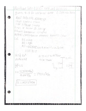
Figure #2: analysis of spring constant.
Analysis #3: The analysis that was done was calculating the thickness of the chassis plate with a 150 N force being applied at the end of the chassis plate the answer came out to be T= 2.55mm so that is the minimum thickness the chassis has to be without breaking. The requirement that was satisfied was the requirement of the length and the width requirement. The problem with using the minimum thickness is that there will not be enough plate to put threads on to mount up all the stuff on top so the thickness needs to be bigger than the minimum thickness.
Figure #3: Analysis of chassis thickness.
Analysis #4: The analysis that was done calculated the force that will be applied to the front bumper after hitting a wall going 20 MPH. the requirement that this fulfills will be the that the RC car will be able to withstand running into a wall at 20mph without breaking the front bumper the force that will be applied to the cars front bumper will be 405.02 N of force so the front bumper needs to be able to withstand 450 N of force just to be safe.

Figure #4: Front Bumper Force Analysis

Figure #5: Distance And Angle Analysis Of Shock
Analysis #6: The analysis that was done was the specific distance the shock will be mounted on the shock mount from the centerline of the shock tower. The analysis fulfilled the requirement of being able to support the weight of the car and not bind up when the car jumps or hits a bump. This analysis fulfills the requirement of the car will ride 4 inches off the ground. The answer that was found is the shock will be mounted 3.5 inches from the centerline of the shock tower on the top of the shock tower. The dimensions on where the shock needs to be mounted will be documented in drawing MSH_20-003
Analysis #5: The analysis that was done this week was the distance and angle the shock will be when fully compressed this analysis fulfills the requirement of being able to support the weight of the car when not being held by a student. This analysis fulfills the requirement of the car be able to ride more than 4 inches off the ground. the angles that were calculated were 30.96 degrees on the bottom and the top is 59.03 degrees this will be used when installing the shock onto the A-arm and onto the Shock tower. The angles and dimensions will be documented on drawing MSH_20-003
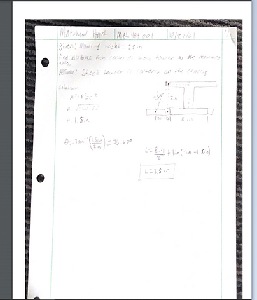
Figure #6: Shock Tower Distance Analysis

Analysis #7: The analysis that was done was the minimum pin diameter for the a-arms with a 90 N shear force being applied. The analysis fulfills the requirement of being able to mount the a-arms to the chassis and the design requirement that the analysis fulfills would be being able to hold the weight of 10 lbs from the car. The minimum diameter that was calculated was 1.9 mm which is 5/64 inches. The dimensions of the pin will be documented in drawing MSH_20-002
Figure #7: Minimum Pin Diameter
Analysis #8: The analysis that was done was the minimum screw diameter that would not strip out with a force of 90 N. The analysis fulfills the requirement of being able to mount up all the parts like the battery bracket, the motor mounts, and the shock towers. The design requirement that the analysis fulfills is that the components of the RC car will not move when a force is applied to the RC car. The Dimensions will be documented in drawing MSH_55-002

Figure #8: Minimum Screw Diameter

Analysis #9: The analysis that was done was the minimum shock tower height to be able so the tower doesn’t break when a force is applied down. The analysis fulfills the requirement of being able to mount the shock to the tower at a height that will hold a force. The design requirement that the analysis fulfills is being able to travel over obstacles without bottoming out. The dimensions will be documented in drawing MSH_20-003
Figure #9: Minimum Shock Tower Height
Analysis #10: The analysis that was done was the minimum A-arm length. The requirement the analysis fulfills is to have an a-arm long enough that your tires wont rub on the chassis when turning. The design requirement is being able to drive over obstacles without bottoming out and also being able to mount the tires to the a-arms. The dimensions will be documented in drawing MSH_20-004

Figure #10: Minimum Swing Arm Length

The analysis that was done was the stresses in the shock tower arms. The requirement the analysis fulfills is to have a thick enough shock tower so the shock tower arms do not snap when under a load. The design requirement the analysis fulfills is the RC car will withstand a drop from 1.5 feet off the ground. The dimensions will be documented in drawing MSH_20-003
Figure #11 Stresses in Shock Tower Arm
The analysis that was done was the Cross-Sectional area of the shock tower. The requirement the analysis fulfills is to the right thickness and height of the shock tower arms. The design requirement the analysis fulfills is that the RC car will be able to withstand a drop from 1.5 feet off the ground without breaking. The dimensions will be documented in drawing MSH_20-003

Figure # 12 Minimum CSA Of Shock Tower